For our first project of this book, we will be creating a mini weather station that will be based on getting readings from the BME680 air quality sensor, which takes pressure, humidity, and temperature readings. We will be using the ESP32 as the microcontroller and a breadboard to connect the circuits.
The following section contains the instructions for this practical exercise.
Hardware
In this book, we use Arduino IDE as our IDE, as it is one of the most popular options for makers and has a large community support. Arduino is an open source piece of software that offers a wide variety of libraries for different types of sensors, devices, and IoT platforms.
For the microcontroller used in our experiments, we use the ESP32 from Espressif. The ESP32 is a powerful microcontroller that comes with integrated Wi-Fi and Bluetooth connectivity and has a strong support base within the IoT community. The board type we use is the NodeMCU ESP32S, which can easily be found on Amazon. There are many different ESP32 boards available, but please note that the pin position can vary between boards, so pay attention to this when using different boards.
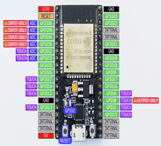
It is important that we familiarize ourselves with the layout of the NodeMCU ESP32S. In Figure 1.11, we provide a pin layout diagram of the NodeMCU ESP32S. You can use this alongside your own direct observations to complete this exercise and gain a better understanding of how the pins interact with the other components that will be used in this chapter and throughout the book.
Do not worry if it looks complicated at first; you’ll get used to it with the practicals that you will undertake along the way!

Figure 1.11 – NodeMCU ESP32S pinout diagram
We can now move forward and read from a sensor. The first sensor we will be working with is the BME680 sensor from Bosch Sensortech. This sensor can be easily found on Amazon, and it can measure relative humidity, barometric pressure, ambient temperature, and gas or volatile organic compounds (VOCs). You can find detailed information about this sensor at https://www.bosch-sensortec.com/products/environmental-sensors/gas-sensors/bme680/.
There are two ways to read the data produced by the sensor: through I2C or SPI. In this experiment, we will be communicating with the BME680 sensor through an I2C connection.
I2C, short for inter-integrated circuit, represents a connection method utilized in serial communication as a bus interface protocol. Commonly referred to as the Two-Wire Interface (TWI), it is a popular choice for short-range communication. This protocol relies on two bi-directional open-drain lines named SDA and SCL. The Serial Data (SDA) line facilitates data transmission, while the Serial Clock (SCL) line conveys the clock signal.
Since the I2C bus can be used to connect multiple devices, each device connected to the bus should have a different address to distinguish it from others.
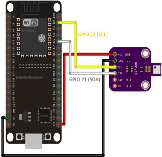
We need to connect the SCL pin of the BME680 board to D22 on the ESP32 board (or IO22 on other ESP32 board), the SDA pin of BME680 to D21 on the ESP32, the VCC of BME680 to the 3V3 pin of the ESP32, and the GND pin on BME680 to the GND pin on ESP32. We can use the protoboard or direct jumper cable between those boards. The connection should look like that in the following figure:

Figure 1.12 – Pinout diagram for attaching BME680 to ESP32
